sheet metal drawing standards
Standard Drawing Sheet Sizes Size Designation Size of sheet in Margins mm Horizontal Topbottom Sides A 85 11 10 6 B 110 170 10 16. This can help achieve a thickness from 116th of an inch to 516th of an inch.
Freelance Sheet Metal Design Services For Companies Cad Crowd
Authorities considering adoption of any standards contained herein should review all federal state local and contract.

. For low carbon steel the minimum radius can be ½ the sheet thickness or 080 mm 003 whichever is greater. Offsets should follow the same sheet metal design guidelines as other bends. Recommended center distance between holes in sheet metal part the recommended minimum distance between two hole centers.
January 1 2020 - GMNA. Sheet Metal March 2008 22. Upper-left corner of the drawing sheet touching the top and left border lines 2.
We will dive into the details of these techniques shortly. Drawing Change Procedure March 2008 24. Why ISO Matters in Custom Metal Fabrication.
For door panels front panels interior panels and racks see document 10-1006 for information on adding a note regarding the implementation EPS-121. The radius of an inside bend should be at least equivalent to the materials thickness to avoid fractures or distortion. When pipes and their relative components are shown on a drawing it is vitally important that the craftsperson can correctly identify their locations and positions.
The symbols for the location of pipes in a building are as follows. If you tell them to do -005 they are either going to ingore your tolerances or they are going to have to clean things up in the machine shop somehow. Scs articulates the cad standards that will enable smacna members and the rest of the aec community to apply cad effectively to mechanical fire protection and plumbing design and construction.
Document 10-0005 Blah Drawing Drafting Standards and Practices for the proper setup of a sheet metal drawing. The charts include fractional decimal and metric dimensions for reference. This includes equipment finishing assembly fastening and the availability of standard dies.
Sheet metal manufacturing is suitable for a range of metal materials. This specification details the requirements for water based drawing compounds that provide additional lubricity to aid in metal forming operations and must be compatible with current production. Order and track sheet metal components online through Komaspecs on-demand sheet metal fabrication platform.
94 The drawing scale for system layout drawings should be coordinated with. The basic sheet metal fabrication techniques include cutting bending punching stamping welding and finishing. Packaging Drawings Not Available 21.
Sheet Metal Drawing Standards. At RapidDirect for instance we produce sheet metal components made from Aluminum Steel Stainless. Extracting Drawings from the Sheet Metal Part Basic Tasks Managing the Default Parameters Editing the Sheet and Tool Parameters Modifying the Bend Extremities.
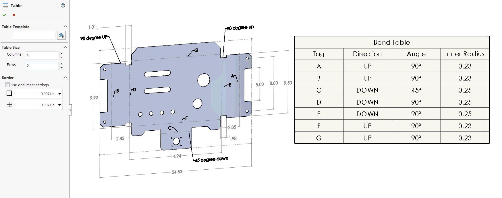
Electrical and Electronics Drawings March 2008 23. Bends in the same plane should be designed in the same direction. Since sheet metal cannot be bent to a 90-degree position without breaking at sharp corners all bends will have an acceptable bend radius.
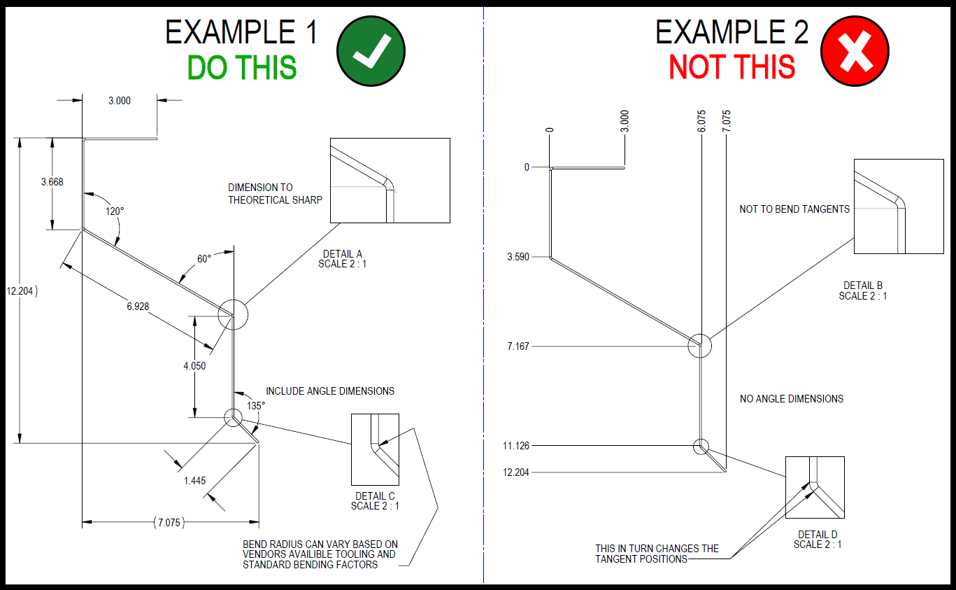
91 For general design work drawing scales shall be full size wherever possible. This video demonstrates how to properly dimension a sheet metal layout technical drawing. 93 When increased scales are necessary the scales shall be 21 51 101 201 and 501.
Confirm the drawing formats with your fabricator to be sure they have no difficulty reading or interpreting your design. 3D CAD files are converted into machine code which controls a machine to precisely cut and form the sheets into the final part. 9981870 - Drawing Compounds Water Based for Sheet Metal.
These factors all play a role in why most manufacturers dont want you to dimension parts in the flat pattern. Abbreviations March 2008. This is on account of the fact that there is a standard allowance for covering wire.
As an example think about a set of school lockers each with a vented door. Inside each standard are detailed instructions and drawings for workers to follow. Although notes on each drawing will differ the first note on ALL sheet.
The Sheet Metal and Air Conditioning Contractors National Association and other contributors assume no responsibility and accept no liability for the application of the principles or techniques contained in this publication. It reviews general dimension standards as well as requirements for. Sheet Metal Roof Coverings.
Critical Dimensions Sheet Metal Forming Outside dimension should be used unless the. This also means that tolerances in the title block of a drawing may be unnecessarily restrictive for certain dimensions and angles while very appropriate for others. The most common sheet metal form is a bend.
Depending on the temperature the process is classified as hot rolling or cold rolling. Sheet metal shops can bend to around -015 accuracy. A description is not available for this item.
By this is meant that the materials dealt with are usually in the form. Lower-left corner of the drawing sheet touching the left and bottom border. Access to company-defined standards tables Dedicated drawing capability including unfolded view.
Bends can give strength and shape to a part and are formed in a machine using bend brakes. However once you expand over all four bends that number increases to a difference of 130 on the overall flat length of the part. ANSI Y1472-1978 Gear and Spline Drawing Standards Part 2.
Bevel and Hypoid Gears ASME B4612002 Surface Texture Surface Roughness Waviness and Lay. By using standard vee-dies cost savings can be realized through economical set-ups. If your order requires exact duplication of materials shapes and cut ISO standards help make that happen.
Sheet Metal DraftingSheet metal drafting is merely the application of the principles of ordinary mechanical drawing to objects which for the purposes of drawing lack thickness. Sheet Metal Fabrication is the process of forming parts from a metal sheet by punching cutting stamping and bending. They are going to.
In this process the sheet metal is passed through a set of rolls. Gauge numbers continue both to thicker and thinner sections but these charts cover the most common ranges. Charts for aluminum steel stainless steel and galvanized steel sheet are presented here with thicknesses ranging from 164 to 14 inch.
Sheet metal parts are known for their durability which makes them great for. The variation becomes larger as the bend angle increases and the part will no longer pass inspection. 92 The recommended reduced scale for fixture designs are 12 15 110 120 and 150.
In hot rolling the temperature is around 1400 degrees Fahrenheit for steel.
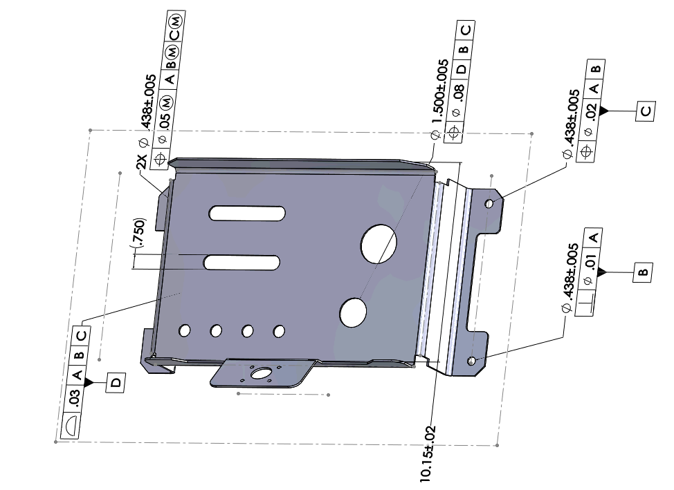
How To Present The Mbd Data Of Sheet Metal Parts Engineers Rule
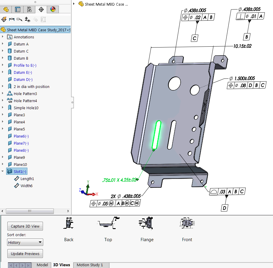
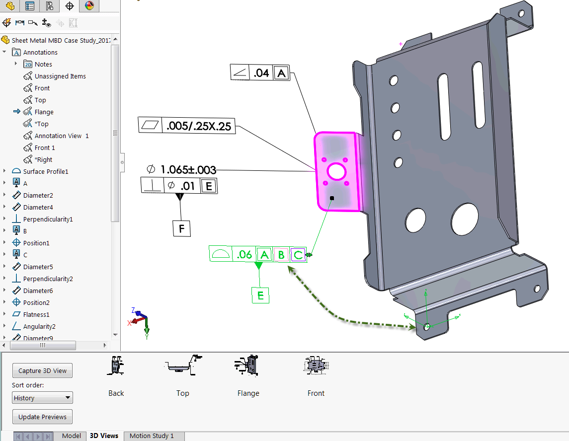
How To Define The Mbd Data Of Sheet Metal Parts Engineers Rule

Solidworks Sheet Metal Drawing Tutorial Bend Line Flat Pattern Unfolded Bend Table Punch Table Youtube
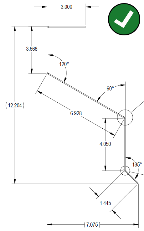
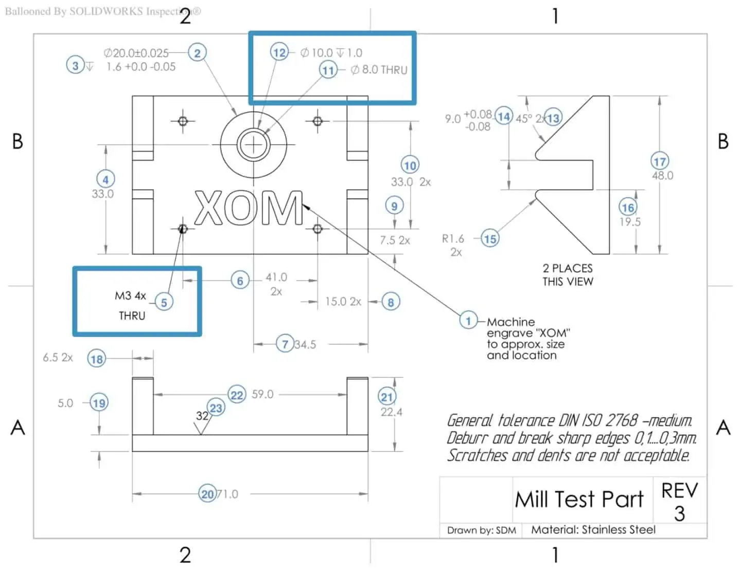
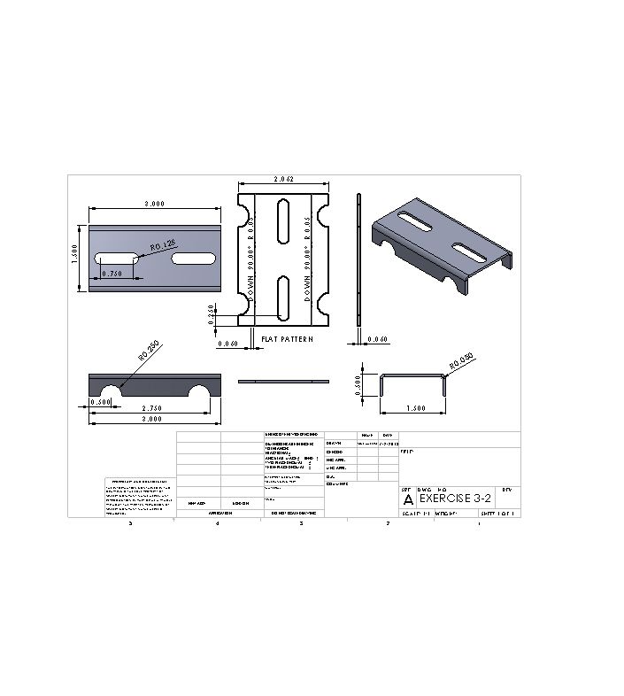
Dimensioning For Ease Of Manufacturing
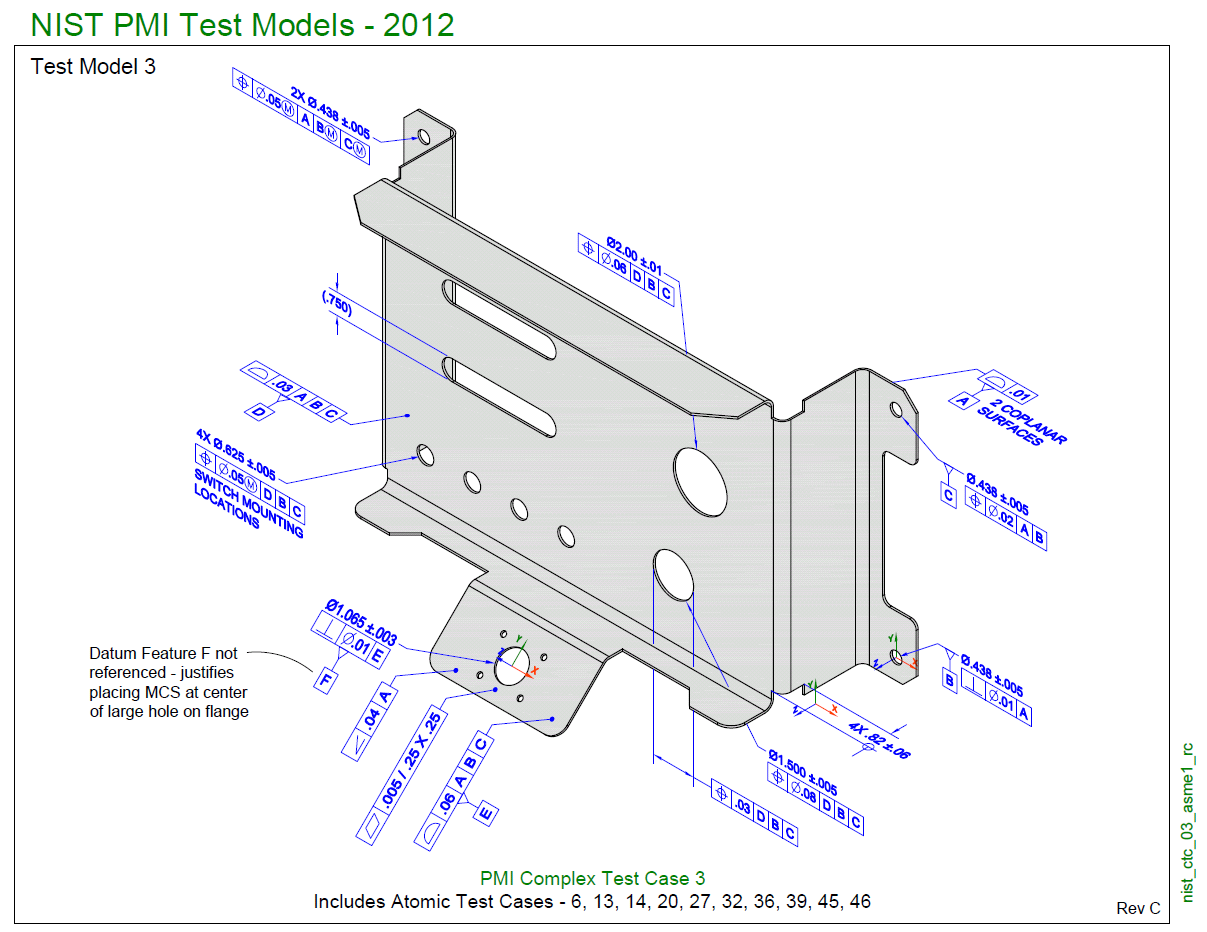
How To Define The Mbd Data Of Sheet Metal Parts Engineers Rule
How To Define The Mbd Data Of Sheet Metal Parts Engineers Rule
How To Define The Mbd Data Of Sheet Metal Parts Engineers Rule
How To Prepare A Perfect Technical Drawing Xometry Europe

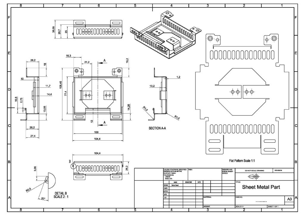
Sheet Metal Dimensional Drawing Example Vista Industrial Products Inc
Dimensioning For Ease Of Manufacturing
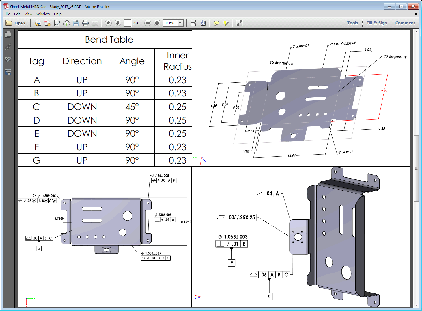
How To Present The Mbd Data Of Sheet Metal Parts Engineers Rule
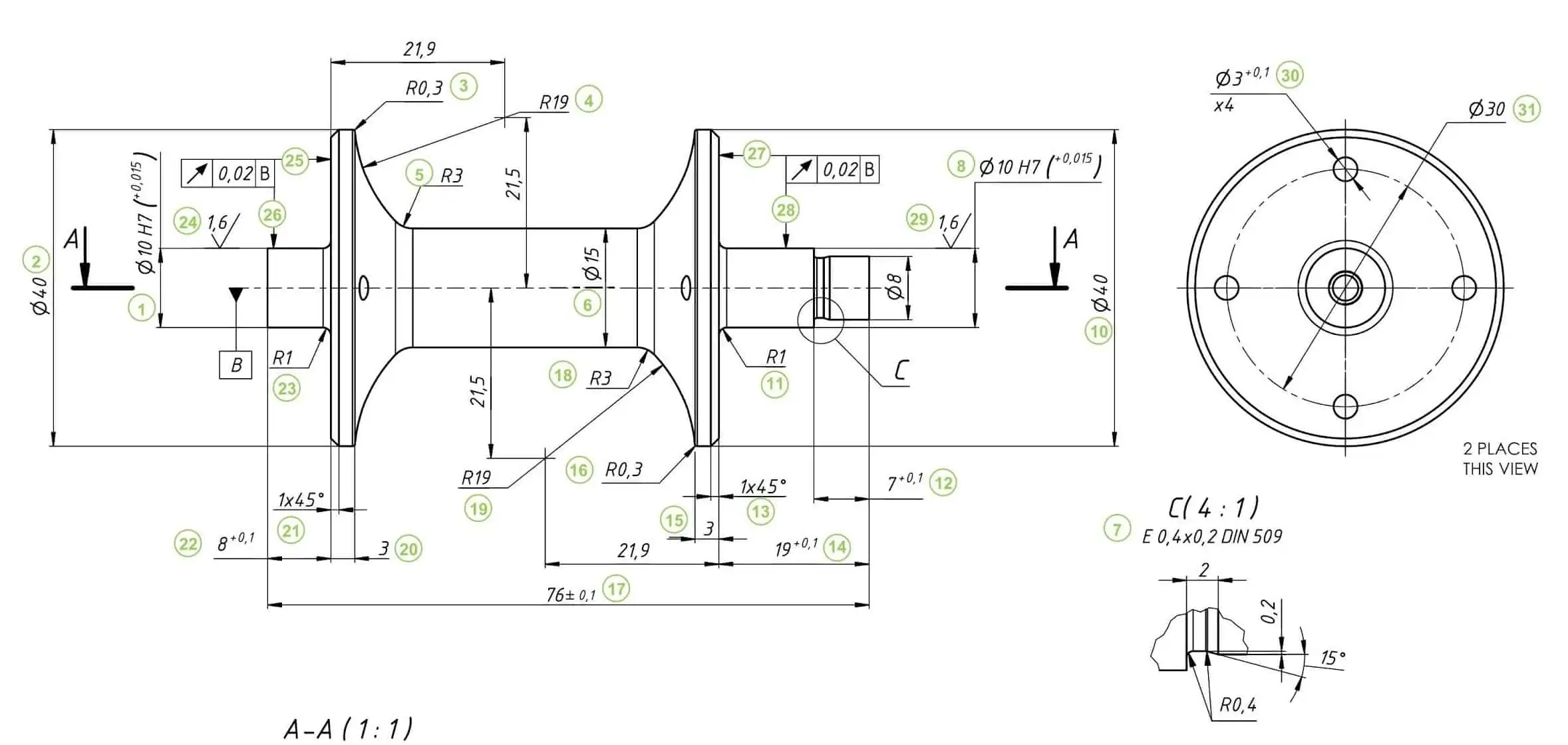
How To Prepare A Perfect Technical Drawing Xometry Europe
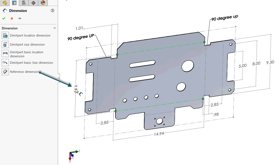
How To Define The Mbd Data Of Sheet Metal Parts Engineers Rule
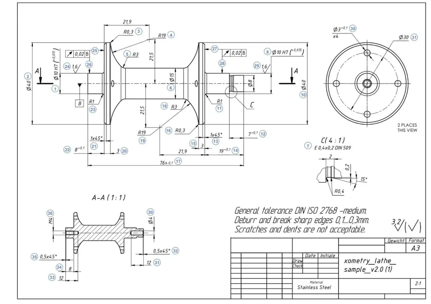
How To Prepare A Perfect Technical Drawing Xometry Europe

Sheet Metal Dimensional Drawing Example Vista Industrial Products Inc
Sheet Metal Drawing Sheet Sheet Metal Drawing Drawing Sheet Sheet Metal
Freelance Sheet Metal Design Services For Companies Cad Crowd

Sheet Metal Dimensional Drawing Example Vista Industrial Products Inc
How To Prepare Drawings For Your Sheet Metal Supplier Komaspec